
Hydropower Consultants Convert a Historic Waterwheel
Converting a Historic Overshot Waterwheel into an Automated Hydropower System in Dorset, England
Project in brief:
Renewables First’s hydropower consultants and engineering team helped adapt a working iron overshot waterwheel from direct mechanical transmission to grid-connected electricity generation.
The project combined rolling-element bearing conversions, a shaft-mounted gearbox, belt-driven generator, rebuilt launder sluice, automated water-level control and grid-synchronising hydro controls, while retaining the historic ironwork and a manual operating option.
Detailed Case Study
Converting a Historic Overshot Waterwheel into an Automated Hydropower System
A commercial watermill in Dorset, England
Project in brief:
Company Name: Lorem Inc.
Date: Jan 2018
Website: www.diviwptheme.com
A working iron overshot waterwheel was adapted from direct mechanical transmission to grid-connected electricity generation. The project combined rolling-element bearing conversions, a shaft-mounted gearbox, belt-driven generator, rebuilt launder sluice, automated water-level control and grid-synchronising hydro controls—while retaining the historic ironwork and a manual operating option.
Key Takeaways
- A historic iron overshot waterwheel was converted from mechanical drive to electricity generation.
- The completed system generates around 13 MWh of electricity per year.
- Design output was approximately 2.7 kW, with operating output rising a little above 3 kW when conditions allow.
- New bearings, a gearbox, generator and automated sluice controls were integrated with the existing historic machinery.
- Electricity is primarily used by the commercial mill, with surplus generation exported to the grid.
A milling history stretching from Domesday to the present day
Although the machinery described in this case study has been modernised, milling at this Dorset location has a much longer history. The mill is recorded in the Domesday Book and was one of several mills operating along the same local watercourse.
The present iron waterwheel dates from 1860. An invoice later found in the Dorset Archive records that it was made by the Maggs and Hindley iron foundry at Bourton and cost £36.
From Somerset milling to the Dorset watermill
The family milling story associated with the present business began in Somerset in 1832, when two brothers leased a mill and developed a trade supplying flour locally and across the Severn to South Wales.
As demand grew, the business moved to a new Bristol mill in 1912 and adopted roller milling, which had by then displaced the more traditional stone grinding in the production of white flour.
The family established its operation at the commercial watermill in Dorset in 1947, initially producing animal feed for local farmers. Seven years later, a major fire destroyed the mill building. No one was hurt, but the damage required a complete rebuild.
The result explains why the building that now surrounds the older machinery has a more mid-20th-century industrial appearance than the mill’s ancient origins might suggest.
Returning to water-powered stoneground flour production
In 1970, production returned to stoneground flour using French Burr millstones and the late-19th-century iron waterwheel. The mill has since continued through successive generations, producing organic stoneground flours for domestic and bakery customers.
That continuity gives the hydropower project particular relevance: it is not an attempt to animate a static exhibit, but the next engineering chapter in a working commercial mill where historic waterpower and modern milling remain closely connected.
Contents
A working watermill with a new role
At a commercial watermill in Dorset, an historic iron overshot waterwheel remained part of the daily flour-milling operation.
Water stored in the millpond could be released through a concrete launder and onto the top of the wheel, where the weight of water in the buckets produced slow, high-torque rotation. The traditional gear and belt-drive transmission then carried that mechanical power into the mill on line-shafts.
Why convert the waterwheel to electricity generation?
The established arrangement was impressive, but it relied on very long flat belts. Problems with those belts created a practical reason to reconsider how the waterwheel’s energy should be used.
Instead of continuing to transmit mechanical power directly to the milling machinery, the project would convert the wheel’s rotation into electricity. That electricity could serve nearby loads within the building, including electric motors used for milling, while surplus generation could pass through the export meter and onto the grid.
This was therefore more than the installation of a generator. It was a waterwheel hydropower conversion involving historic machinery, confined access, substantial mechanical torque, water control, automatic operation and grid connection.
The challenge was to create a modern, reliable small hydroelectric system without stripping away the character or useful fabric of the original watermill.
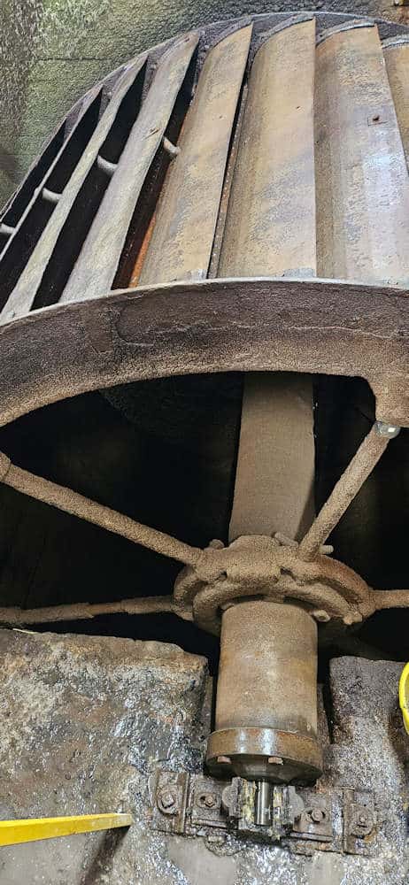
the historic all-iron overshot waterwheel, showing its buckets, shrouds, main shaft and bolt-on stub axle
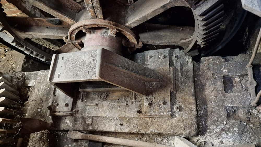
the drive-end pit wheel, the covered plain bearing and the narrow gap between the pit wheel and wheel-pit wall.
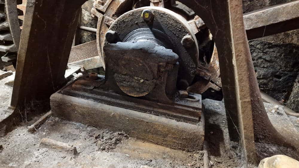
the drive-end pit wheel, the covered plain bearing and the narrow gap between the pit wheel and wheel-pit wall.
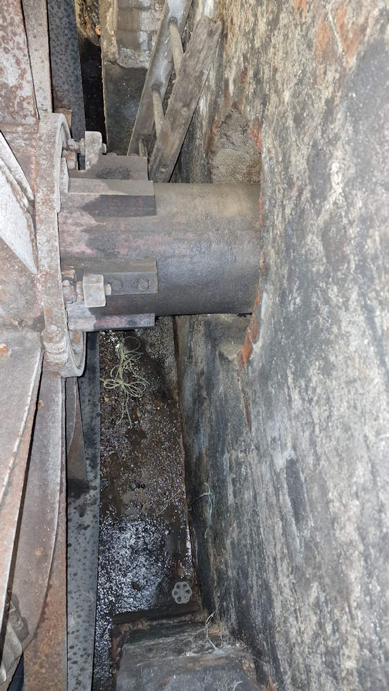
the drive-end pit wheel, the covered plain bearing and the narrow gap between the pit wheel and wheel-pit wall.
How our hydropower consultants approached the conversion
The starting point for Renewables First was understanding what could be retained, what needed adapting and how the mechanical, hydraulic and electrical elements would work together as one system.
That meant considering the existing shaft and bearings, available installation space, water control, generator speed, grid connection and automated operation before individual components were altered.
Understanding the existing waterwheel and transmission
The waterwheel was made entirely from iron, including its buckets, shrouds and main shaft. A particularly useful feature was the bolt-on stub axles at each end of the shaft.
For a waterwheel-to-electricity project, that detail created an important engineering opportunity. A replacement stub axle could be manufactured to suit a modern bearing and, at the drive end, extended to carry a gearbox.
Preparing the bearings for continuous operation
The original bearings were white-metal plain bearings. At the wheel’s low rotational speed, this simple arrangement could operate for decades, provided it received regular grease – approximately once a week in this case.
However, an automatically controlled hydropower installation is expected to run continuously. Reliable 24-hr operation, reducing friction and creating a dependable long-duration bearing arrangement were therefore central to the conversion.
Working with the original mechanical transmission
On the drive side, the pit wheel had previously turned a vertical ‘wallower’ gear, transmitting the power to a vertical shaft through the mill. The wallower had been disconnected and leant against the wall some decades before.
Instead, an outer ring fixed to the pit wheel drove a large flat-belt pulley connected to a line shaft and the existing milling machinery. Some pit-wheel teeth were missing, but the teeth were not part of the later belt-drive arrangement.
The task was to introduce a modern gearbox and electrical generator onto the end of this traditional assembly.
Engineering within a confined space
Space was limited. Behind the pit wheel, the gap to the masonry wheel-pit wall was only around 300–400 mm. Yet that narrow space would become useful: it was sufficient to position support equipment beneath the main shaft while the original bearing and stub axle were removed.
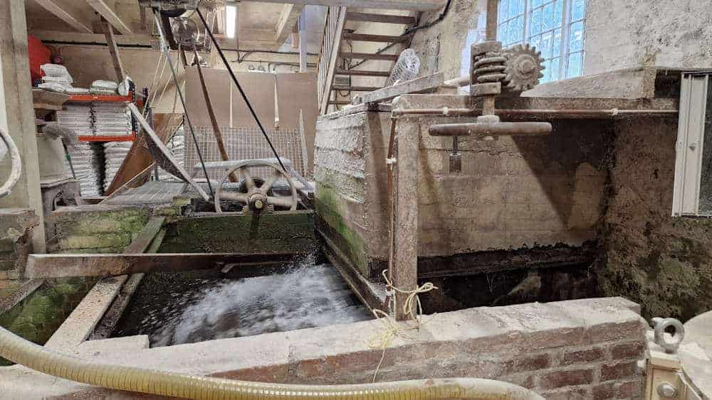
The concrete launder
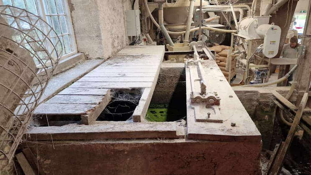
the letterbox-like discharge onto the top of the wheel
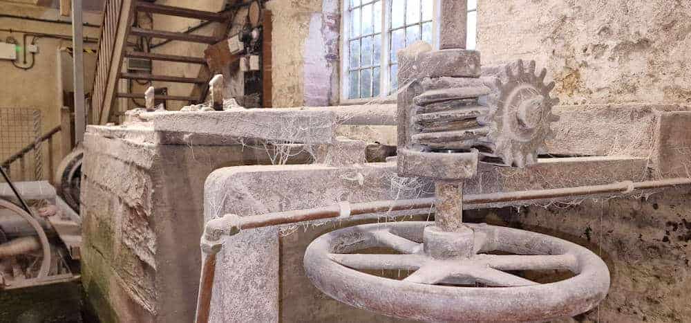
and the historic handwheel, worm drive and rack-and-pinion sluice-lifting mechanism
How the overshot waterwheel was supplied with water
The concrete launder carried water from the millpond into the building and discharged a controlled sheet of water onto the top of the overshot wheel. The quantity of water was governed by a sluice gate inside the launder. Above it, the existing handwheel drove worm gearing and a rack-and-pinion mechanism to raise or lower the gate.
The original gate was timber and was in poor condition. It also slid directly against the concrete without a purpose-made frame, allowing significant leakage at the sides and bottom. That was unsuitable for an automated waterwheel system, which needed predictable water control and the ability to close the supply properly. The sluice would therefore need to be rebuilt as well as automated.
Retaining manual sluice control
At the same time, the project aimed to retain the handwheel and historic lifting mechanism. A dog-clutch would allow the new actuator to engage with the old mechanism, while still permitting manual operation when disengaged. This approach kept the visible historic machinery substantially as it was and made the modern intervention an addition rather than a wholesale replacement.
Converting the non-drive-end bearing
Work began by replacing the plain bearing at the non-drive end of the waterwheel. The wheel’s weight had to be supported before the bearing housing could be removed.
A large lifting strap was placed around the main axle to carry the load, after which the plain bearing and housing were taken out and then the six bolts securing the stub axle to the iron main shaft could be removed.
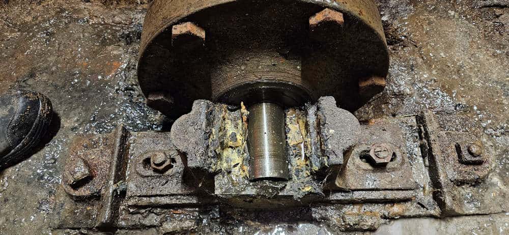
the original non-drive-side stub axle and plain bearing
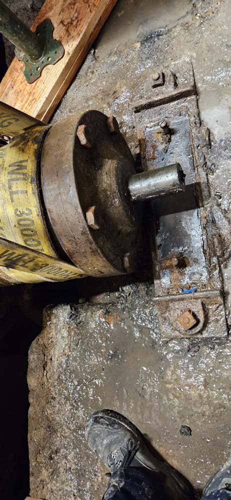
the wheel supported during removal
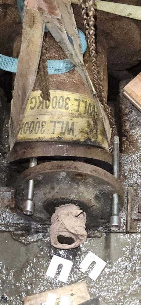
the six-bolt stub-axle connection being dismantled.
Preparing the retained components
Preparation of the retained components was meticulous. The stub axle’s mating face, its bearing surfaces, the corresponding face on the main shaft and the bearing support plate were cleaned and smoothed. Clean, accurately prepared mating faces were essential before the re-assembly could begin.
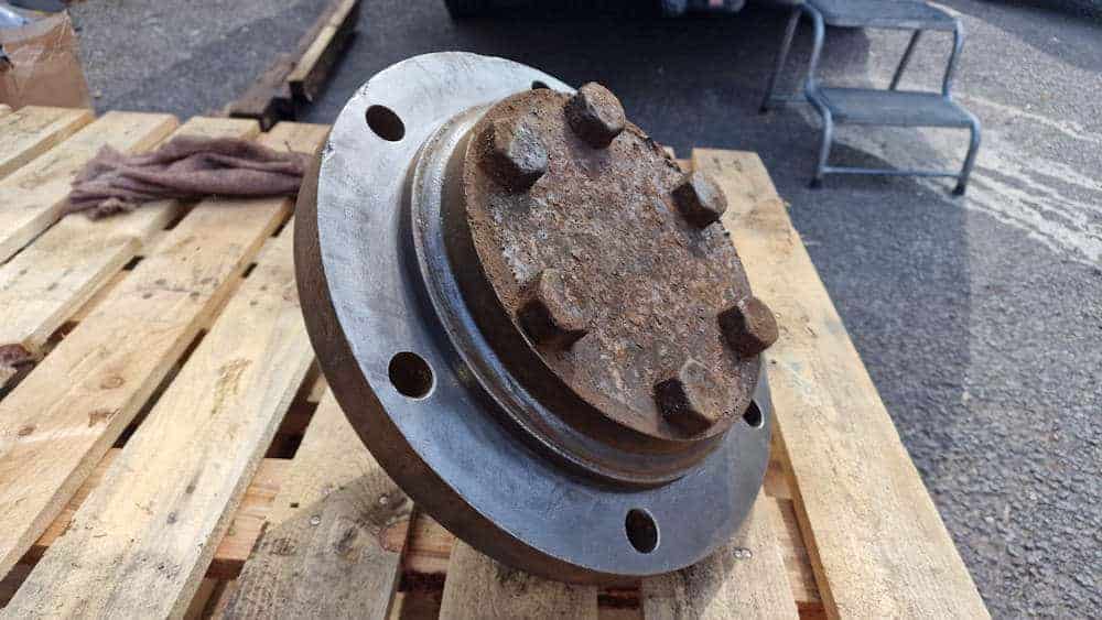
both sides of the cleaned stub axle
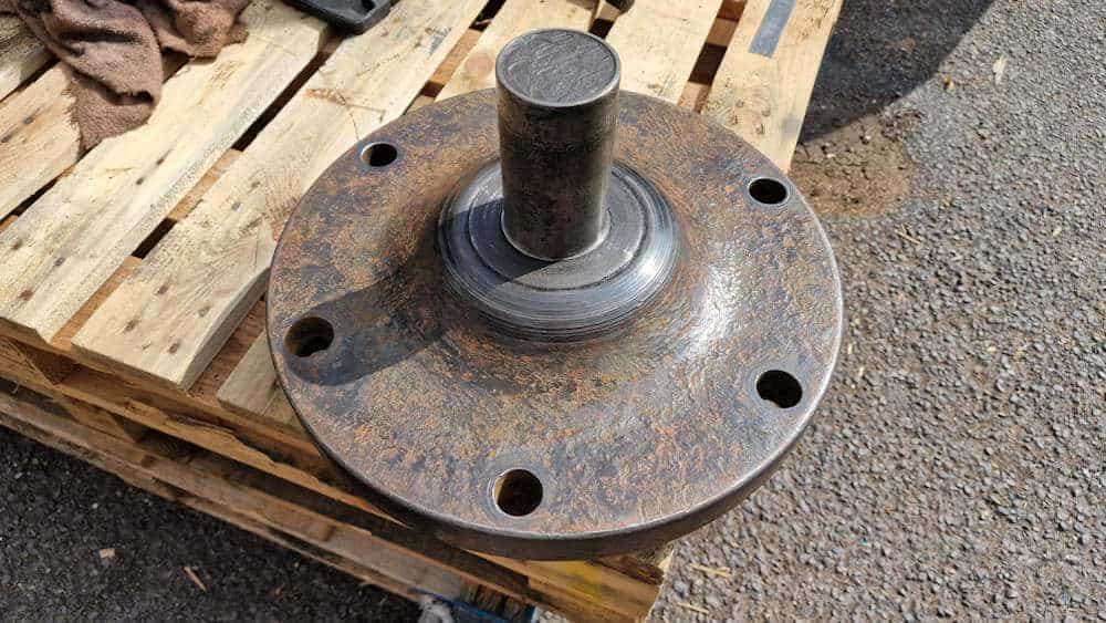
other side of the cleaned stub axle
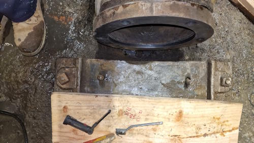
both sides of the cleaned stub axle, followed by cleaning of the waterwheel main-shaft mating face and bearing support plate.
Installing the rolling-element bearing
The original stub axle was then bolted back onto the main shaft. A new stainless-steel bearing baseplate was installed beneath it, followed by a rolling-element bearing located onto a tapered sleeve. Spacers and seals completed the arrangement, and the bearing housing was packed with grease before its cap was fitted.
A spring-loaded automatic lubricator was added to dispense grease over approximately a six-month period.
Finally, a stainless-steel cover was installed to shield the new bearing from the worst of the dirt and water spray. The conversion reduced rolling friction and removed the concern that the original bearing might overheat during continuous unattended operation.
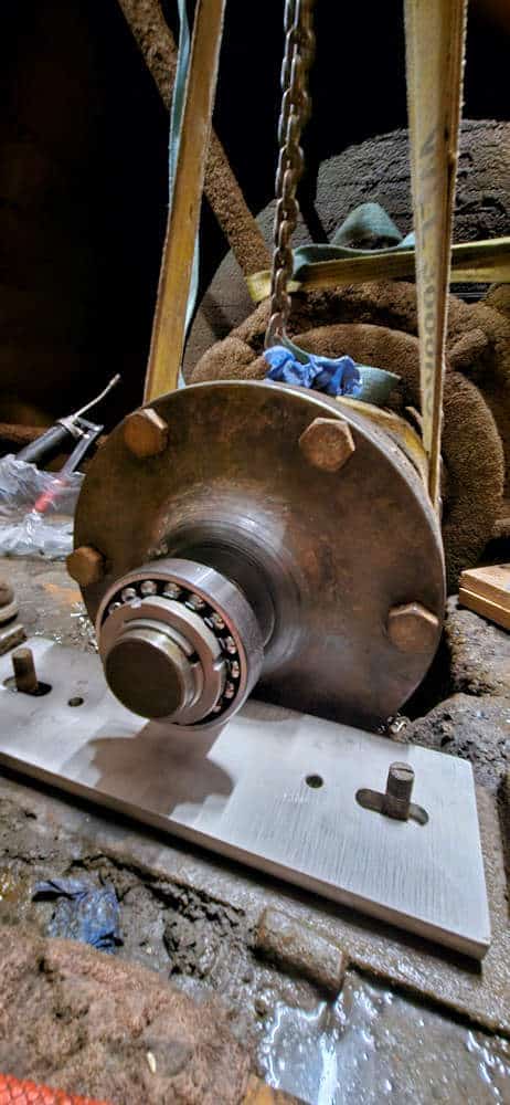
reassembly of the stub axle
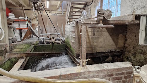
the concrete launder
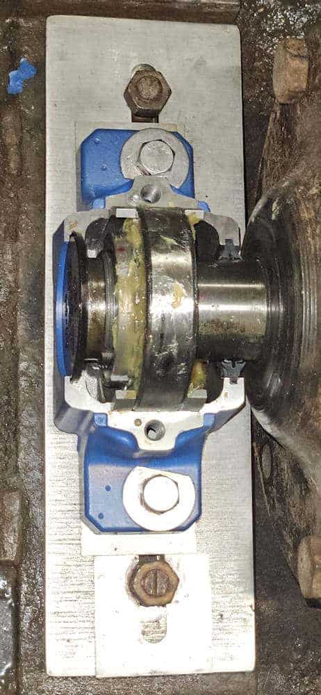
rolling-element bearing
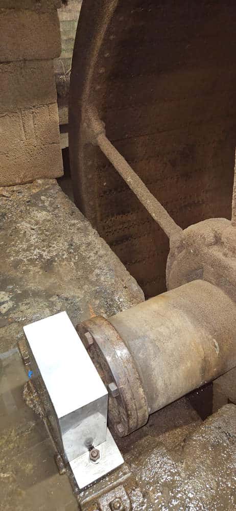
new stainless-steel protective cover
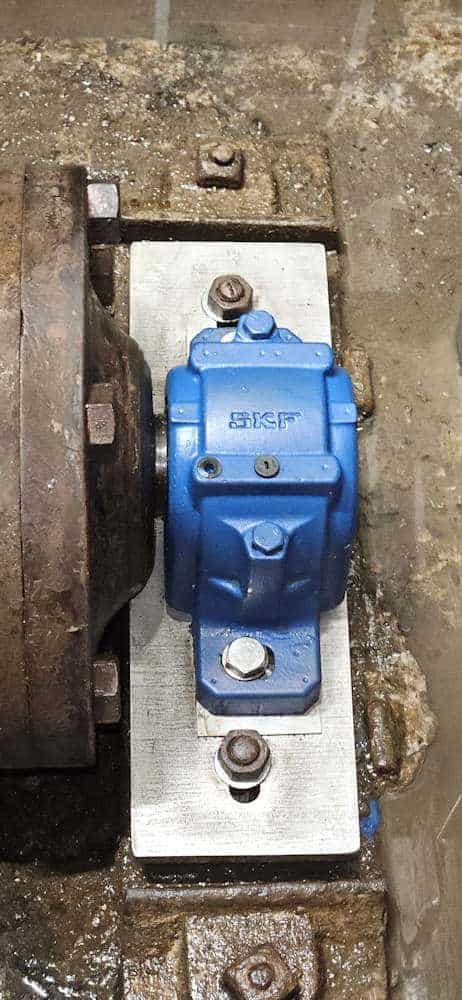
Bearing housing cap fitted.
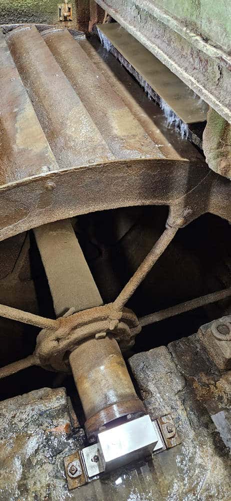
the completed non-drive-end bearing arrangement.
Engineering the drive end for electricity generation
The drive end required the same move from a plain bearing to a rolling-element bearing, but it also had to carry the new powertrain. The cast-iron bearing cover was removed and retained on site. It was part of the historic machinery, but it obstructed the proposed gearbox and generator position and was not needed in the new configuration.
Within the narrow space between the pit wheel and the masonry wall, a large steel post and hydraulic bottle jack were installed to support the waterwheel shaft. With the bearing unloaded, the old housing, plain bearing and short bolt-on stub axle could be safely removed.
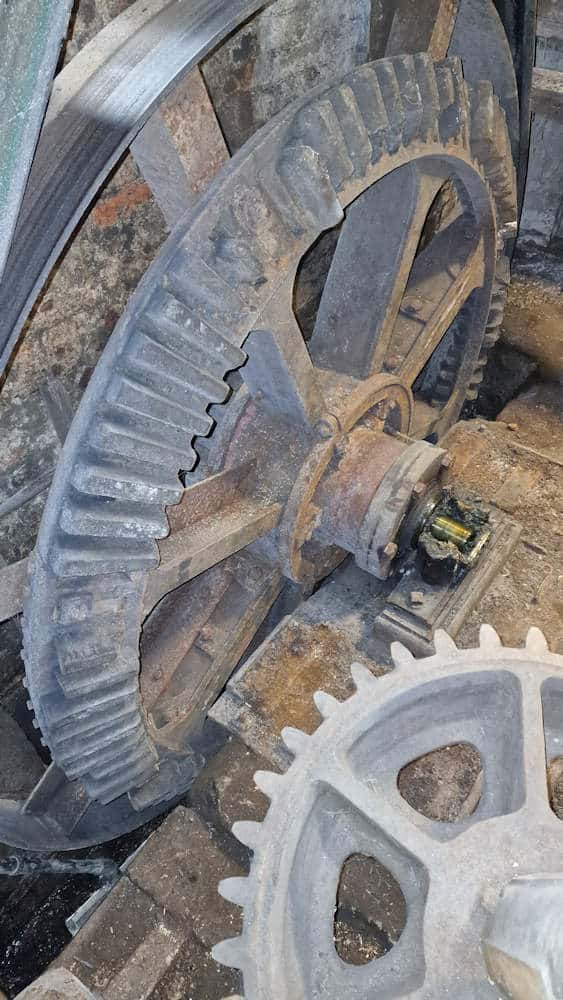
the exposed drive end and pit wheel
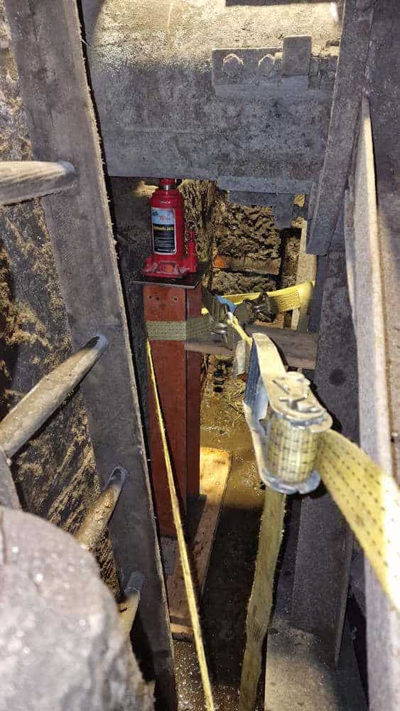
the steel post and hydraulic jack supporting the wheel
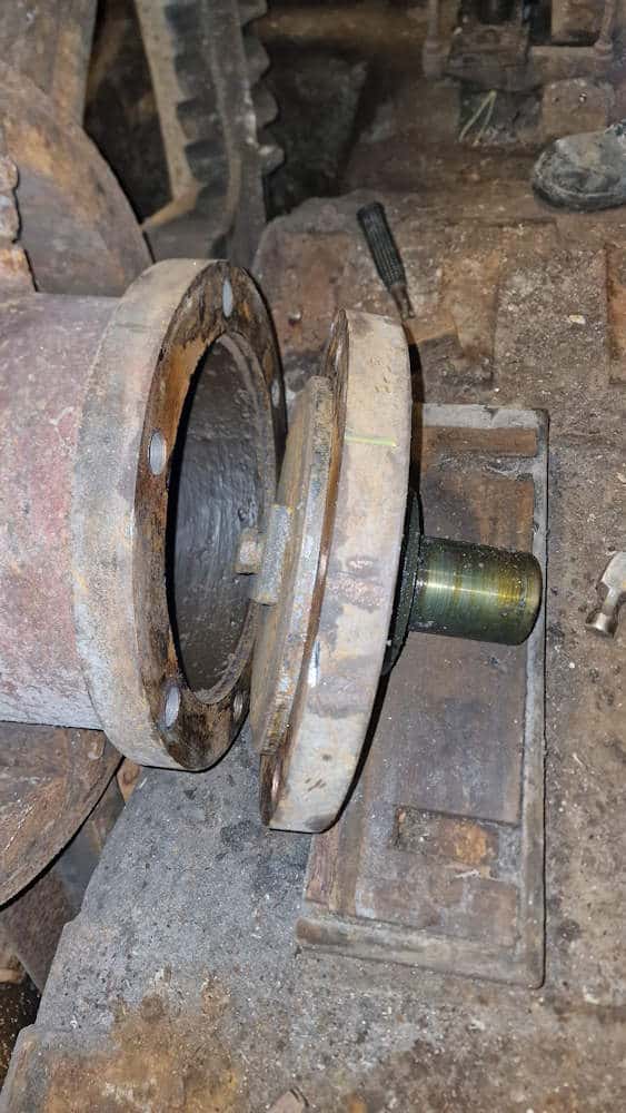
the old plain bearing, housing and short stub axle.
A longer bolt-on stub axle for the shaft-mounted gearbox
The bolt-on construction made it possible to design a longer replacement stub axle. A pattern was produced, the component was cast in spheroidal graphite iron, and it was machined to fit the existing shaft, modern rolling-element bearing and new gearbox. Its extra length provided the shaft space that the generating equipment required.
Once bolted to the main shaft, the long stub axle was paired with a new stainless-steel bearing support plate. The rolling-element bearing and housing were assembled, locked into position, packed with grease and closed with the housing cap.
Both ends of the waterwheel could now run on properly mounted rolling-element bearings suited to continuous hydropower operation.
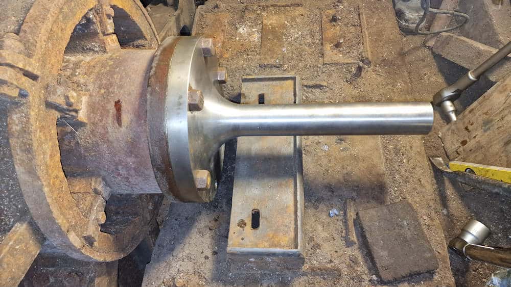
the newly cast and machined long stub axle,
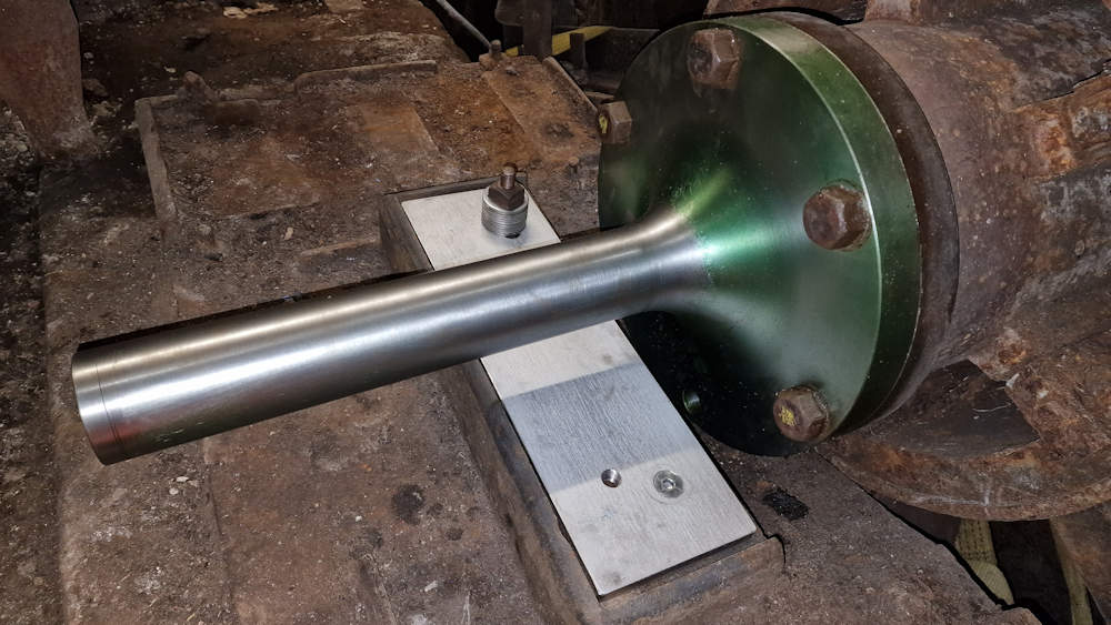
the newly cast and machined long stub axle, its installation with the stainless-steel support plate
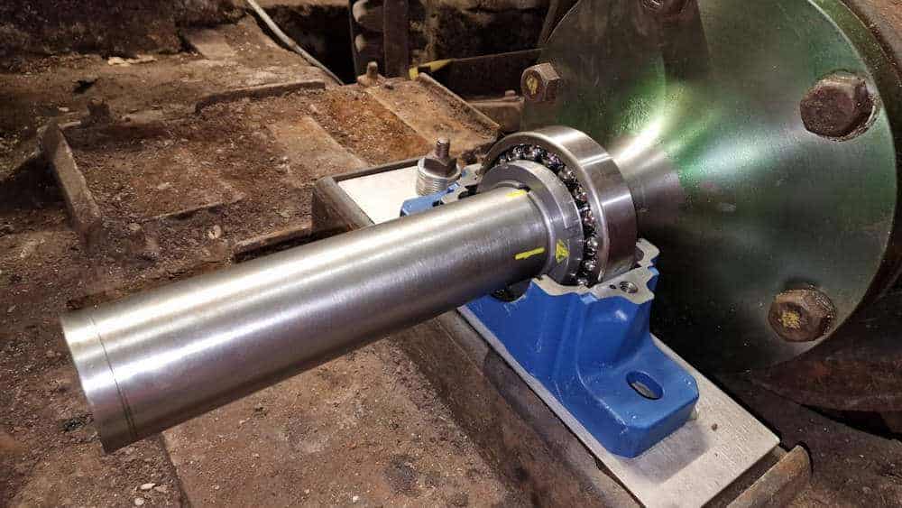
drive-end rolling-element bearing being assembled, greased and capped.
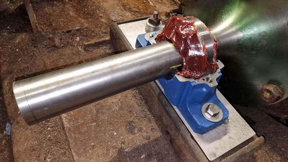
New bearing packed with grease
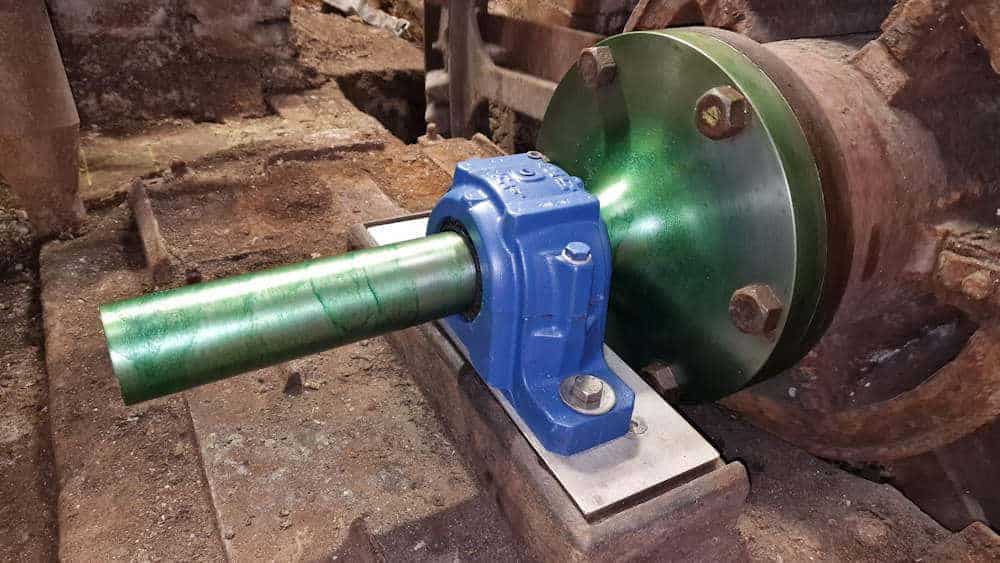
Housing cap fitted to the new bearing
Using a shaft-mounted gearbox to handle waterwheel torque
An overshot waterwheel rotates slowly but produces immense torque. That makes direct connection to a conventional belt-drive impractical. The solution was a shaft-mounted gearbox, fitted directly over the extended stub axle and restrained by a substantial torque-arm anchored to the masonry of the wheel pit.
The shaft-mounted arrangement avoided a separate base-mounted gearbox and eliminated the coupling and alignment work that would otherwise have been required. Sliding directly onto the shaft made the gearbox inherently concentric with it. The torque-arm then provided the reactive torque without asking the gearbox casing and fixings to the masonry to perform that role.
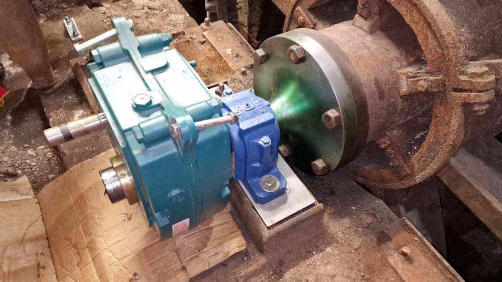
installation of the shaft-mounted gearbox
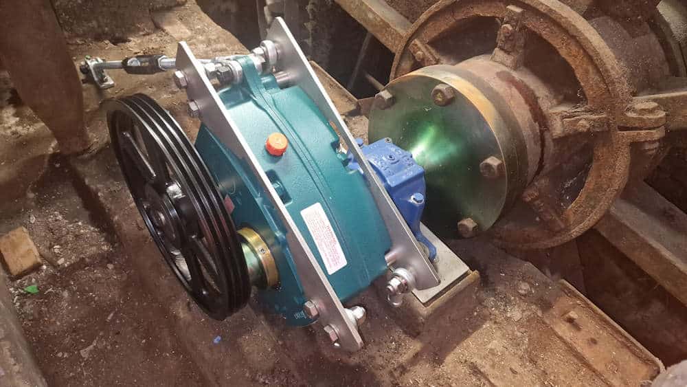
Drive pulley fitted onto the gearbox output shaft
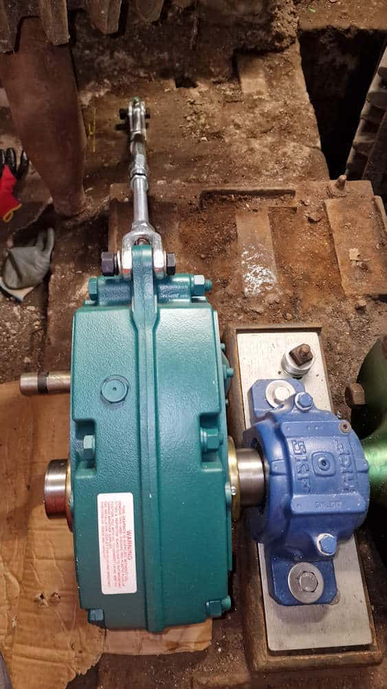
New gearbox fitted with torque arm
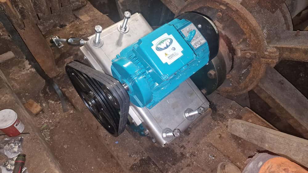
Generator baseplate, generator, driven pulley and drive belts
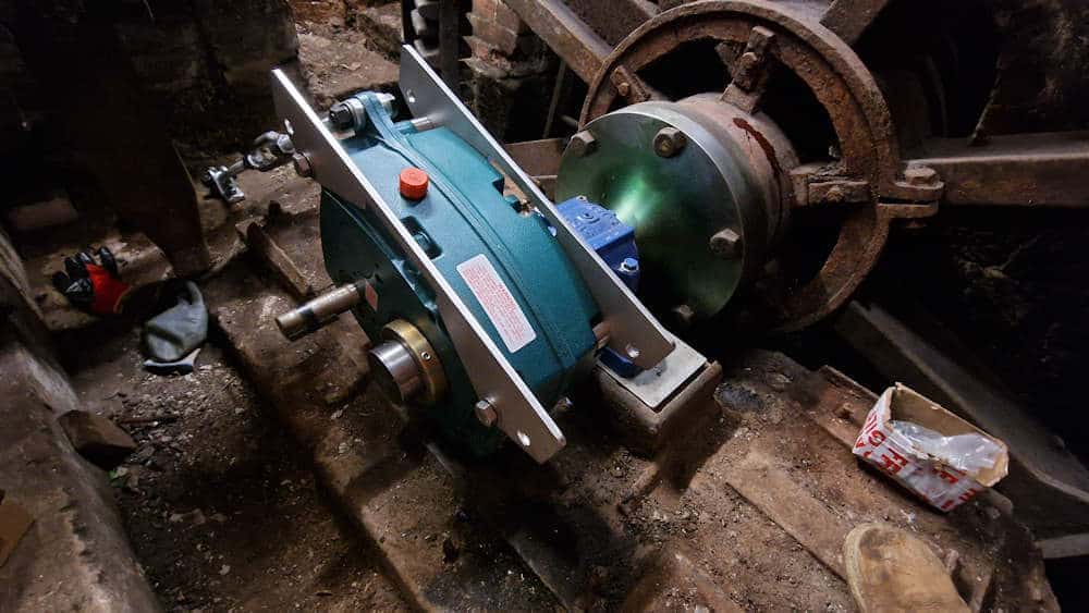
Side plates fitted to the gearbox to allow fitting of the generator baseplate
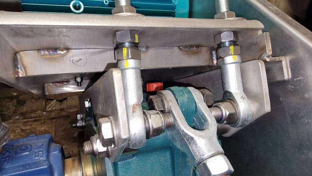
Close-up of the torque-arm connecting to the gearbox
Increasing speed for the generator
The gearbox increased rotational speed by approximately 20:1, trading the waterwheel’s very high torque and low speed for a faster, lower-torque output. A three-V-belt transmission then provided a further speed increase of approximately 4:1, raising the speed to 1,500 rpm for connection to the generator.
Side plates attached to the gearbox supported the generator baseplate above it, creating a compact installation within the restricted pit-wheel room. With the generator wired, the drive-end assembly formed a complete mechanical path from the historic waterwheel to the generator.
Low-speed wheel rotation entered the gearbox; the gearbox raised the speed by around twenty times; and the belt drive increased it again to the generator’s operating speed. The substantial steelwork and fasteners reflected the forces involved, but the finished arrangement remained compact and straightforward.
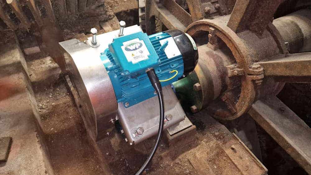
The finished drive-end with gearbox and generator
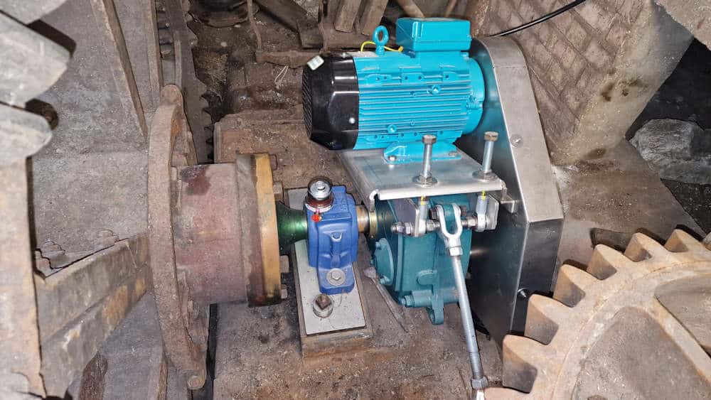
The finished drive-end assembly viewed from the other side - note the torque-arm and grease lubricator
Rebuilding the launder sluice for accurate flow control
Mechanical generation was only one half of the project. A reliable automated hydropower system also needs to control the water delivered to the overshot wheel.
Before work could begin inside the launder, the channel had to be dewatered. A timber cofferdam covered with plastic sheeting was constructed to hold back the millpond water, while opening the existing front sluice allowed the working area to drain.
Installing the new sluice frame
The available space was tight – about two metres wide with around one metre of working length.
Within that space, the old timber gate was removed, and a new stainless-steel sluice frame was carefully installed. Considerable attention was given to keeping the frame vertical and parallel.
Fixing holes were drilled into the old concrete and the anchors were resin-fixed. After mechanical fixing and shimming, the perimeter gaps were sealed with quick-setting underwater putty.
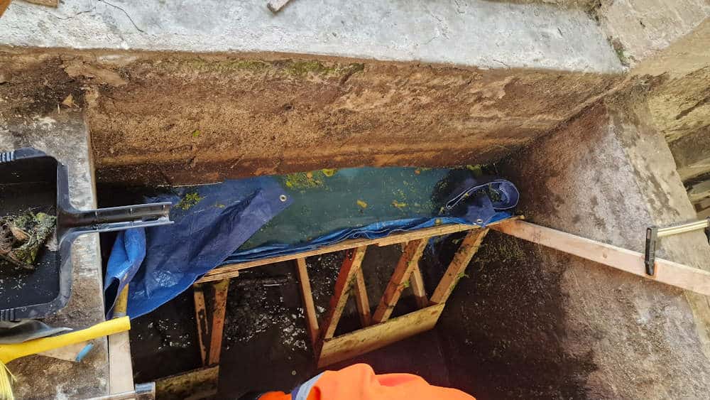
Before work started on the launder sluice a timber coffer dam had to be installed to hold the water back
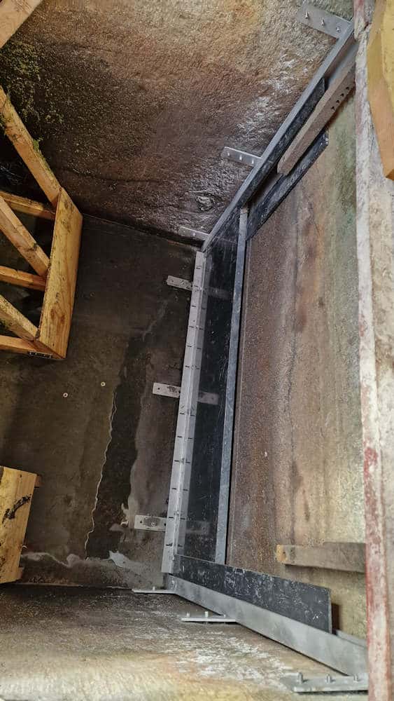
Fitting the new stainless-steel launder sluice frame inside the old concrete launder
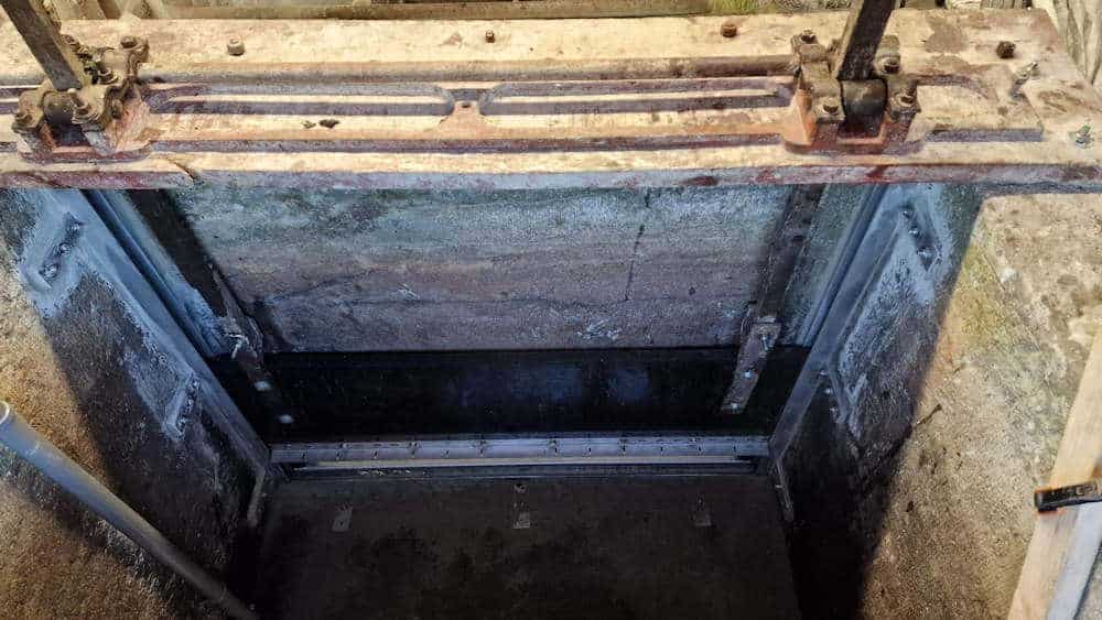
New sluice framework in place with the gaps around the framework sealed-up with underwater putty
Retaining the historic rack-and-pinion mechanism
The replacement sluice blade was manufactured from HDPE. The original iron racks were bolted to the new blade, preserving the historic rack-and-pinion lifting system while giving the gate a smoother, better-sealed sliding surface. A stiffening strip across the lower edge prevented vibration or resonance.
Unlike the former timber gate sliding against concrete, the HDPE blade now travelled within a purpose-made stainless-steel frame. When closed, the assembly could seal properly against the concrete. That improvement was essential for repeatable automatic flow regulation.
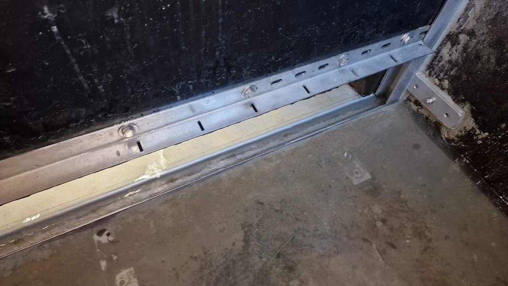
The new launder sluice gate with stiffening brace to prevent it vibrating in operation
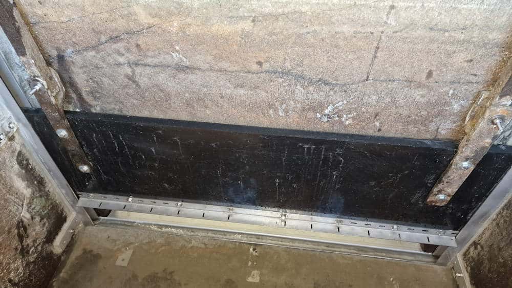
The completed new launder sluice gate, attached to the historic lifting mechanism
Water-level sensing and automatic sluice actuation
A stilling tube was installed just upstream of the sluice gate. Inside it, a water-depth pressure sensor measured the upstream level and sent a 4–20 mA signal to the hydro controller. The tube provided a suitable sensing location immediately before the controlled outlet.
Maintaining a constant upstream water level
The control objective was to maintain a constant upstream water level. If the level fell below its set point, the controller would close the sluice slightly, reduce the flow over the wheel and allow the level to recover.
If rainfall increased the available river flow and the upstream level began to rise, the controller would open the sluice further, use more water and generate more power.
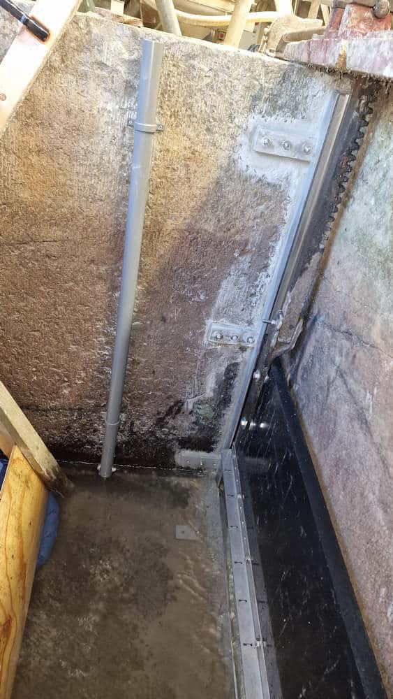
Stilling tube installed just upstream of the sluice gate for the upstream water level sensor
Automating the historic handwheel
Outside the launder, the retained handwheel was automated using a high-torque 24-volt DC motor with an integral gearbox. A high-ratio belt-and-pulley system increased the available torque again.
The mechanism turned at only about 2 rpm, but that slow movement delivered the force needed to start and continue moving the gate, especially from the fully closed position.
Preserving manual operation
A dog clutch connected the actuator to the historic handwheel. Engaged, it allowed the motor to turn the handwheel, worm drive and rack-and-pinion system in the same way as a person would operate them.
Disengaged, it preserved the ability to move the sluice manually if required. A stainless-steel box guard enclosed the completed actuator mechanism and prevented contact or entrapment.
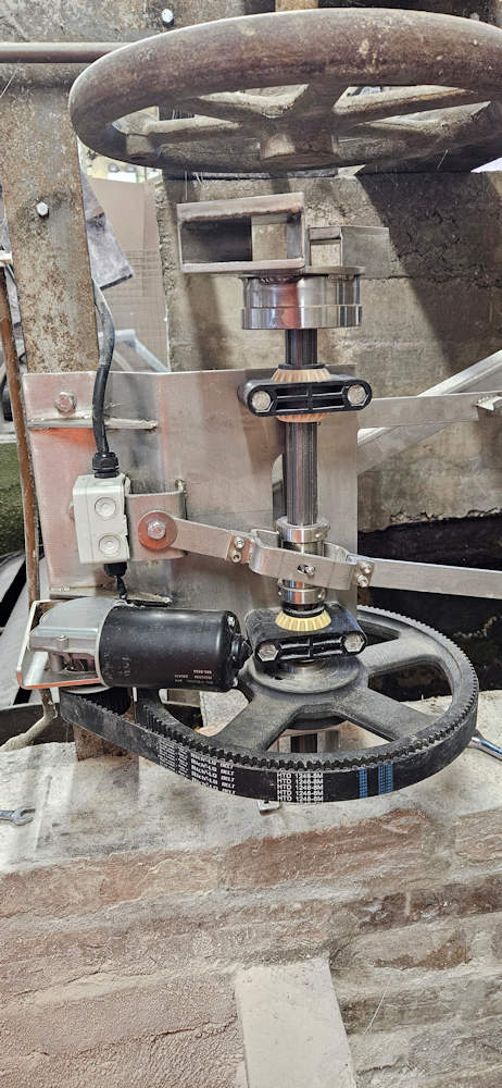
Automating the sluice using a DC motor, gearbox, belt-drive and dog clutch, with a disengagement mechanism
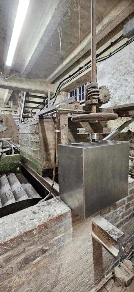
The completed sluice actuation mechanism inside a box-guard enclosure
Setting the sluice travel limits
Inductive proximity switches detected the ends of the sluice gate’s travel. Projecting bolt heads on the moving rack approached the sensors when the gate reached its open or closed limit.
These signals told the controller when to stop the sluice motor, protecting the mechanism and giving the control system definite fully open or closed gate-position information.
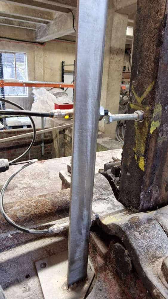
Proximity switches used to detect the sluice gate open and closed positions
Hydro controller, grid synchronisation and electrical use
The generator cable entered the hydro controller, and the controller’s outgoing power cable connected to the local distribution board. Generated electricity could therefore serve the nearest electrical load in the building. When there was no local demand, the electricity passed through the export meter and onto the grid. Because on-site demand was very low overnight, most overnight generation was exported.
Integrating the sluice and water-level controls
The same controller operated the 24-volt sluice actuator. Reversing the DC polarity changed the actuator direction to open or close the gate. Inputs from the proximity switches reported the fully open and fully closed positions, while the 4–20 mA water-level signal provided the upstream water level measurement used to regulate the flow rate.
Managing the grid connection
The controller managed both the hydropower generation system and the grid connection process and met G99 requirements. It was fully configurable so that its behaviour could be programmed for the site and tuned during operation. The installed controller was manufactured by Sustainable Control Systems in Herefordshire.
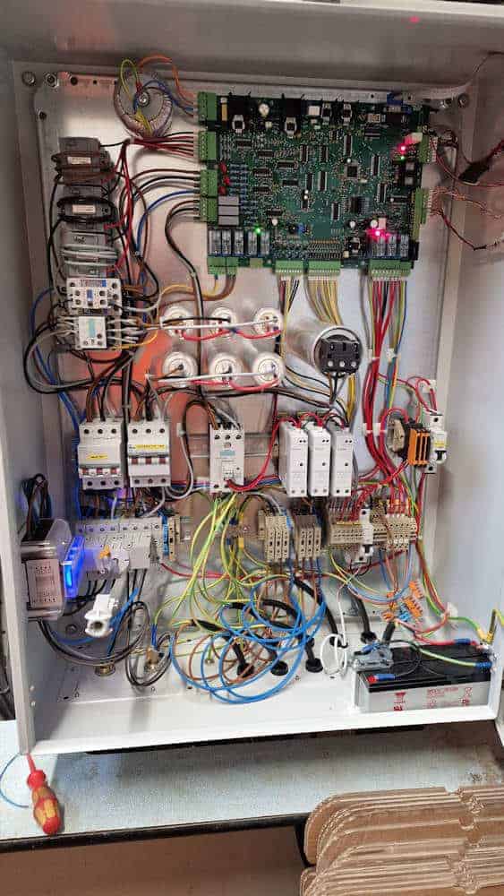
Inside the controller
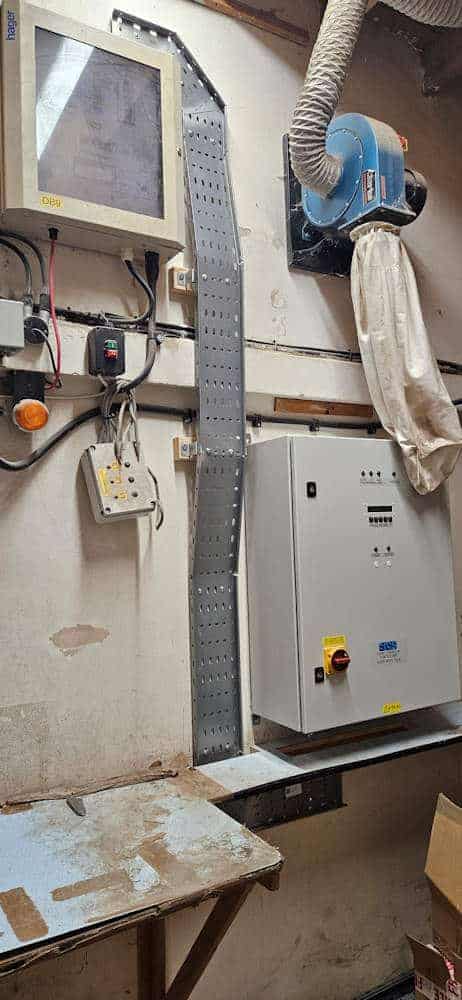
Hydro controller on the wall (lower right)
How the automated waterwheel hydropower system starts
At start-up, the dog clutch is engaged so that the DC motor can turn the historic handwheel. The handwheel drives the worm gearing and rack-and-pinion mechanism, lifting the HDPE sluice gate.
Water begins to discharge from the bottom of the sluice and through the lower end of the launder onto the wheel.
Starting the waterwheel
The first movement is counter-intuitive: as the initial water fills the buckets, its weight briefly pulls the waterwheel backwards. With more flow, the water catches the wheel correctly and it begins rotating in the intended direction.
Synchronising the generator
The controller then monitors the electrical frequency produced by the generator. Below 50 Hz, it admits more water to increase wheel speed. Above 50 Hz, it reduces the water supply to slow it down.
Once the frequency reaches 50 Hz and the generator waveform is synchronised with the grid, the controller closes the contactor and connects the generator. It then supplies additional water so that the system begins producing electricity.
Continuous operation and responsive water management
In normal service, the system operates automatically and continuously. It holds the upstream water level at its set point while generating electricity.
Available energy is used within the commercial watermill when a local load is present and exported when it is not.
Responding to changes in water availability
Gate opening is not fixed. If more water becomes available, the controller can open the sluice further until the upper bolt reaches the proximity switch and confirms that the fully open limit has been reached.
In the recorded operating view, the sluice is approximately two-thirds open and the inductive switch arrangement can be seen working. The characteristic ‘thudding’ of the waterwheel remains audible, but the system runs smoothly.
Inside the pit-wheel room
The pit-wheel room is reached through a very small doorway and down a short staircase. The former wallower wheel remains visible in the foreground – it is no longer used, but it is too heavy to remove and has been left leaning against the wall providing a clear reminder of the mill’s former mechanical transmission.
Historic machinery alongside modern generation equipment
Alongside it, the new bearing, shaft-mounted gearbox, generator and V-belt drive can be seen operating. The low-speed input enters the gearbox and emerges at approximately twenty times the speed and much lower torque.
The belts raise the speed further to 1,500 rpm for the generator. The installation uses a grid-excited generator, so generator frequency is fixed by the grid and the generator ultimately governs the waterwheel speed.
The gearbox torque arm is fixed to the pit-room masonry to provide reactive torque. In the recorded view, the automatic lubricator does not contain grease (yet), although the bearing itself has been fully packed and can operate safely. The overall result is a neat, simple mechanical arrangement working in close proximity to the retained historic machinery.
Power output and annual renewable energy production
The hydropower design was assessed using a gross head of 3.923 m and an estimated net head of approximately 3.5 m after allowing for hydraulic losses.
Mean flow was estimated at 0.120 m³/s from catchment modelling. For the maximum design condition, flow over the waterwheel was taken as 1.3 times the mean flow, giving 0.156 m³/s.
Calculating the maximum design output
The electrical output estimate then allowed for efficiency at each stage of the conversion. Waterwheel efficiency was assumed to be 60%, followed by 98% for the gearbox, 93% for the belt drive and 93% for the generator. Applying those efficiencies to the available hydraulic power gives an estimated maximum electrical output of approximately 2.7 kW.
Design calculation. P = ρ × g × Q × H × η. Using Q = 0.156 m³/s, H = 3.5 m and combined efficiency η = 0.60 × 0.98 × 0.93 × 0.93 gives approximately 2.72 kW, reported as a 2.7 kW maximum design output.
Actual operating output
Actual operation has shown that the system can produce a little over 3 kW. The most likely operating context is a period when additional flow is available after rainfall, allowing more water to pass over the wheel than the maximum-flow assumption used in the design estimate.
Annual electricity generation
Across a year, the installation generates about 13 MWh of electricity. That is equivalent to the stated annual electricity use of approximately 4.6 average UK homes.
In this commercial setting, however, the more direct benefit is that generation is largely consumed on site by the modern electric-motor-powered milling machinery. Power is exported only when generation exceeds the mill’s immediate electrical demand.
These figures place the project in a useful perspective. The instantaneous output is modest compared with large hydroelectric plant, but the system uses an existing water resource and established mill infrastructure to generate continuously when conditions allow.
Its value comes from dependable annual energy production, high on-site utilisation and the successful adaptation of a working historic waterwheel.
The completed historic waterwheel conversion
The finished project demonstrates a practical route for converting a suitable historic overshot waterwheel into an automated, grid-connected renewable energy system. The waterwheel and its iron shaft were retained. Historic water-control ironwork remained in use.
Manual sluice operation was preserved through an engageable dog-clutch. At the same time, the installation gained rolling-element bearings, automatic lubrication, a shaft-mounted speed-increasing gearbox, a generator, accurate sluice control, upstream water-level sensing and a configurable hydro controller.
Why the existing shaft was so important
The key enabling feature was the steel main shaft with bolt-on stub axles. It allowed the non-drive end to be rebuilt around a modern bearing and the drive end to receive a specially cast, longer stub axle capable of carrying the gearbox.
A waterwheel with an old wooden shaft would not offer the same foundation. Where a sound steel shaft and adaptable stub-axle arrangement exist, however, there can be considerable flexibility in designing a waterwheel generator system.
Treating the hydropower system as one integrated project
This project also shows why a successful watermill hydropower retrofit must be considered as one integrated system. Reducing bearing friction supports continuous running. The gearbox and belt drive translate low-speed high-torque from the waterwheel into high-speed low-torque for the generator.
The rebuilt sluice creates a leak-free and controllable water flow. Water-level sensing protects the upstream level while responding to changing flows in the watercourse. Grid synchronisation governs connection, and automatic control balances available water with electricity production. Each element depends on the others.
Preserving the working history of the mill
Most importantly, the result does not disguise the working history of the mill. The old pit wheel, rack and pinion, handwheels, worm gearing and other machinery remain in place alongside the modern bearing housings, stainless-steel fabrications, generator and controller.
It is an engineering conversion in which historic waterpower machinery continues to do useful work – now as an automatically controlled hydroelectric generation system for a commercial watermill in Dorset.
Talk to our hydropower consultants about your site
Have an existing waterwheel, mill or potential hydropower site you would like to put to productive use? Renewables First can help assess the water resource, existing infrastructure and engineering requirements involved in developing or upgrading a hydropower system.
To discuss the practical potential of your site, contact Renewables First’s hydropower consultants today.
Frequently asked questions
Can an old waterwheel be converted to generate electricity?
Yes, where the existing machinery and waterwheel shaft provide a suitable engineering foundation. In this project, the all-iron overshot wheel had a steel main shaft and bolt-on stub axles. Those features allowed modern rolling-element bearings, a longer drive-end stub axle, a shaft-mounted gearbox and a generator to be installed. A wooden shaft would not be suitable for the same approach.